^
Testing tandem solar cells

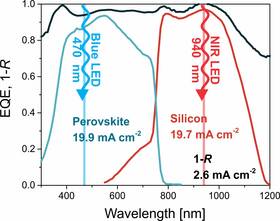
When it comes to testing tandem solar cells such as perovskite/silicon cells, the classic solar simulator might not be the most suitable type of light source. The reason is the difficulty in setting the correct levels of light excitation for each sub-cell and therefore their desired photogenerated current. Often, multiple light source solar simulators are used instead but the calibration of such a setup is iterative and time consuming.
To make the testing of tandem solar cells more convenient, we have developed a special test setup that addresses these issues. The BCLED setup is based on a bichromatic LED light source which ensures simple and fast calibration, facilitating the J-V measurements. Furthermore, the BCLED setup was designed primarily to serve as a long-term stability test setup. Special design considerations were taken into account which assure that the light source degradation is mitigated as much as possible (see below). Compared to the conventional xenon and halogen light sources that reach to around 1000 hours of operation, the lifetime of the BCLED light source extends to ten times more. Therefore, using the BCLED setup in conjunction with our μMPP tracker, long-term stability measurements can also be easily performed.
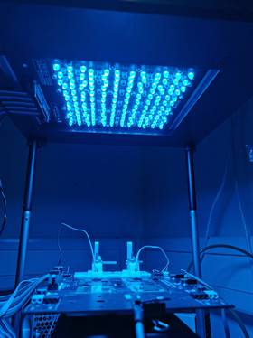
The BCLED consists of three key parts: a bichromatic LED light source, a device holder and a controller. The bichromatic light source provides two spectrally completely independent light sources, the device holder accommodates four lab-size devices (encapsulated or non-encapsulated) and the controller ensures that the entire setup can be controlled through a computer and that the measurement processes can be automated.
^
Components

Bichromatic LED light source
- blue LED array: 12 x 12 matrix, peak wavelength @ 470 nm, maximal power approx. 890 W/m2 @ T=25 °C, inhomogeneity = approx. 2.7 %
- IR LED array: 7 x 7 matrix, peak wavelength @ 940 nm, maximal power approx. 960 W/m2 @ T=25 °C, inhomogeneity = approx. 3.9 %
- independent control of both LED array light sources
- all LEDs in the array work at the same working point which greatly mitigates the effect of LED degradation on light distribution inhomogeneity
- very small LED half-angle of 20 ° assures perpendicular illumination/irradiation and no large-angle effects in the tested devices
- efficient cooling of the light source assures low working temperatures and prolongs light source lifetime
- temperature monitoring of LEDs and their current sources provides additional information about possible functionality issues
Device holder
- 7.5 x 7.5 cm2 large homogeneously illuminated area, accommodating up to for 4 laboratory devices
- simplifies the 4-wire measurement connections to either encapsulated or non-encapsulated devices
- vacuum suction provides good thermal and electrical contact to the holder
- temperature regulation with minimal electromagnetic interference (EMI) to the tested devices allows noise-free measurements of small signals
- provides a matrix of photodiodes for reference irradiance measurement for both blue and IR light source independently
- provides a matrix of RTD temperature sensors for temperature measurement of the tested devices
Setup controller
- manual or electronic (software) control of the irradiance intensity
- monitoring of all the setup parameters via software on a computer
- measurement procedures and calibrations can therefore be automated (e.g. automated irradiance level setup to ensure current matching of the cells)
- monitoring and logging of the reference irradiance levels and temperatures on the sample holder
- various digital interfaces provide good connectivity and extendibility (USB, RS485, I2C, 1 wire)


