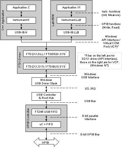
(Move cursor over image to highlight explanation.)
|
LabVIEW Application typically communicates with instruments using instrument drivers.
These are collections of sub-VIs. For example driver for power supply could have Initialise.VI, SetVoltage.VI, etc.
Example: To set voltage to 3.3 V, the application calls SetVoltage.VI(USB-GPIB::5,3.3).
5 is instrument address and 3.3 is float value.
|
Instrument driver converts request to strings that are sent to (or read from) the instrument through GPIB controller driver.
This is also a collection of sub-VIs (USB GPIB Initialise.VI, USB GPIB Write.VI, USB GPIB Read.VI, etc).
More information can be found in the manual.
Example: Instrument driver calls USB GPIB Write.VI(USB-GPIB::5,"VOLT 3.3").
|
|
Operation is similar for application written in C++.
Collection of VIs in LLB is replaced with collections of functions in header file.
|
GPIB driver performs addressing and converts data to GPIB controller protocol and communicates to the controller
through either FTDI driver' API calls or virtual COM port (VCP) implemented with FTDI driver.
Although named the same, it is a different driver depending on FTDI interface.
The driver also waits for acknowledgements from the controller. More information on the protocol can be found in the manual.
In the first case data is sent to the controller using FT_Write() (and read using FT_Read()) function in FTD2XX.DLL,
while in the other case it is simply sent to the serial port.
Example: First addressing is performed: "IBc\x25\r".
Data is sent using BSC protocol: "IB\x10\x02VOLT 3.3\x10\x03".
On the end de-addressing is performed: "IBc\x3F\r".
|
|
FTDI driver passes data through Windows USB driver stack to the FTDI chip in the GPIB controller.
|
Microcontroller reads data, formatted using controller protocol, from the FTDI FIFO chip.
The microcontroller executes received commands and passes data to the GPIB bus.
Example: "IBc\x25\r" -> L5, "IB\x10\x02VOLT 3.3\x10\x03" -> "OUT 3.3", "IBc\x3F\r" -> UNL.
|
